Inside the Rug Railway tender
I was going to wait a decent amount of time before dismantling the Rug Railway engine to find out it’s secrets, but a couple of things happened. The big Hantarex monitor my mad mate gave me suddenly started emitting a fusillade of sparks from somewhere around the back of the tube, (that’s a high-voltage part, I believe), so I couldn’t sit and just watch TV; and the box of damaged repairable clockwork trains I bought off ebay arrived. So I cleared up a little more space around the rug, set up a small track, and played some more.
I found that none of the buttons work from stationary except slow forwards or slow reverse. After pressing one of these buttons, none of the other buttons work until after a set time period. I managed to determine that this period finished on the tenth chuff, and so managed to learn how to control the engine a little better for shunting.
The method I finally established is to run the engine forwards so that when it is reversed towards an intended stop point it will travel for at least 10 chuffs. This means making longer engine movements than are ideal, but it is only a toy, after all. If you want realism, go and join a preservation society.
After playing around for a while, I had another idea. I couldn’t alter the length of the minimum on time, (10 chuffs), but if I could slow the engine down, it would travel less distance in the space of 10 chuffs. I had charged up all of my nicads, so the only thing I could think of doing was taking out two of the 6 batteries and replacing them with run-down non-rechargeable batteries. It seemed to work; the sound effects were more muted, the engine seemed to run slower but still emitted some smoke, and I tried to convince myself that it was more controllable when shunting. After a while I realised that the voltage drop had decreased the sensitivity of the receiver diode, and when the range decreased to less than six inches I found myself no longer able to stop the engine.
I got out the screwdriver and the optovisor. The tender body can be detached from the chassis by undoing the 4 crosshead screws at the corners, leaving the screws holding the couplings and wheels alone. The top of the tender then lifts off to the extent that the wires allow, enough for some photographs.

The loudspeaker and on/off switch wires can be seen running to the chassis, and the battery wires are visible. The blue and red wires coming off the middle of the PCB run to the diode receiver. A 4-wire ribbon cable runs to the engine, to power the motor, headlights, and smoke system.

Of these 4, I suspect one is a common return, two are for motor speed (marked M+ and M-), and the remaining wire drives the headlamps. There are plenty of small resistors and transistors scattered around the board.
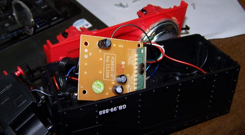
After undoing the 2 screws securing the CB I carefully flipped it over, expecting to see a microprocessor, or at least a PLA chip, but no, just 3 capacitors and a strange device on a daughter board.
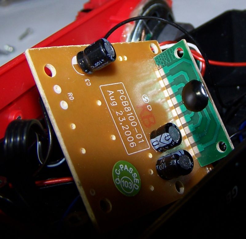
Here’s a better look at that daughterboard, and I’m guessing that’s a chip beneath the black encapsulation dome. With no identification details it’s not going to be possible to look up characteristics in manufacturers tables, so this is going to have to be a black-box exercise, unless anybody reading this blog knows a lot more than I do. From the letters on it, I suspect it to be the Infrared diode receiver chip.
What the circuit board has to implement is
- Distribute the 6 volt battery supply to the receiver diode and chip.
- On power-on, initialise and make a bell clang noise.
- Wait for a signal from the receiver diode and process it.
- If the current state is stopped, ignore any command unless it is slow forward or slow reverse, when it activates, and starts a timer.
- If the current state is not-stopped and the timer has not completed, ignore the command.
- If the current state is not-stopped and the timer has completed, try to obey the command, which will be one of
- Stop : always obey
- Whistle : toggle whistle state or switch from other sound to whistle
- Bell : toggle bell state or switch from other sound to bell
- rail clatter : toggle rail clatter state or switch from other sound to rail clatter
- Slow-forward : only obey if the current state is Fast-forward
- Slow-reverse : only obey if the current state is Fast-reverse
- Fast-forward : only obey if the current state is Slow forward
- Fast-reverse : only obey if the current state is Slow reverse
I have to assume that the chip also decodes the signal received from the diode.
So that leaves me wondering if one of those 3 capacitors is part of an R-C circuit implementing the minimum on time. Assuming it starts in a discharged state, it will take a certain amount of time to charge to a voltage level, which it will then maintain until grounded. Any thoughts out there?
I did a bit of searching on the web and found out that the set is distributed by a company in Hong Kong but manufactured in China, but I don’t see this as being immediately helpful. But who knows, I might have Chinese readers one day.
The set, by the way, is a Royal Express 8104. Looking round the Golden Bright distributors website, I found they did 6 different sets. As far as I could tell from the small photos, the engine and wagons are the same in all sets, the track and accessories vary. So the next question is, where can I get some more points for it?
